Always test all products before mounting on your vessel, or other hard to reach location.
You should always connect your sensor at your desk/bench with an M12 connector and only 12 VDC to verify that it is operating correctly before connecting to your vessel N2K network.
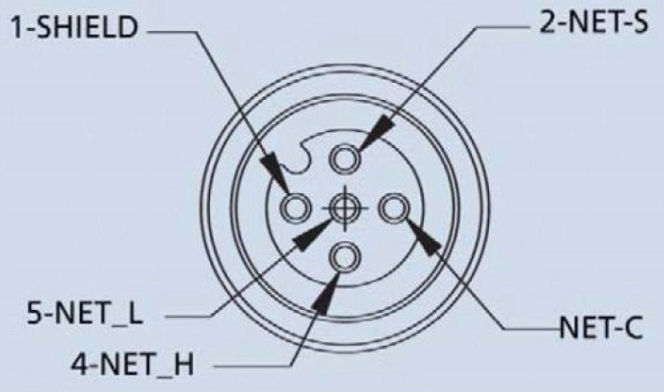
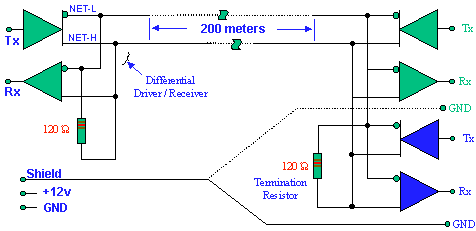
The images below illustrates the wiring of an N2K network. For testing at your bench, only pins 2 and 3 are used.
- Cable shield should be connected to vessel ground at only one point.
- 2-NET-S is nominal +12VDC.
- NET-C is GND or negative, of the nominal 12VDC vessel power.
- Network Low.
- Network High.
The triangles belong to the N2K equipment proper. But the termination resistors and shield and power connections should be useful. You can use common 1/4 watts 1% resistors and connect them directly inside field assembly M12 type A connectors along with the cable wires leaving the connectors. You can also connect a red and black wires, at pin2 and pin3 accordingly. Please include an appropiate fuse (3 Amp fast blow fuse is ok for only Wallis&Gill 2 or 3 device only network).
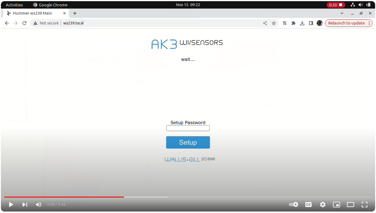
After connecting nominal 12VDC to your sensor via an M12 NMEA2000 connector, watch the quick web configuration video below...